cn380_Design_2026-03-23
[!links] Parent: COMP 380 MOCCOMP 380 MOC\[!links\] School Notes Spring 26 MOC Class Notes cn380_Design_2026-03-23 Midterm Study Midterm Study Guide Midterm Practice Problems
Class Diagrams DiagramsClass Diagrams Diagrams\[!links\] Parent: COMP 380 MOC Analysis And Design Model 737 Activity Diagram 737 * Not the same as UML class diagram. Swimlane Diagram 929 State Diagram Pasted image 20260323195219.png * Not attributes. * Scoped to a singular class, not the program as a whole. Sequence Diagram (partial) Pasted image 20260323195348.png
Fundamental Concepts
- Abstraction: data, procedure, control
- Architecture: The overall structure of the software
- Patterns: "conveys the essence" of a proven design solution
- Separation of concerns: Any complex problem can be more easily handled if it is subdivided into pieces.
- Modularity: compartmentalization of data and function.
- Hiding: controlled interfaces
- Functional independence: single-minded function and low coupling.
- Refinement: elaboration of detail for all abstractions.
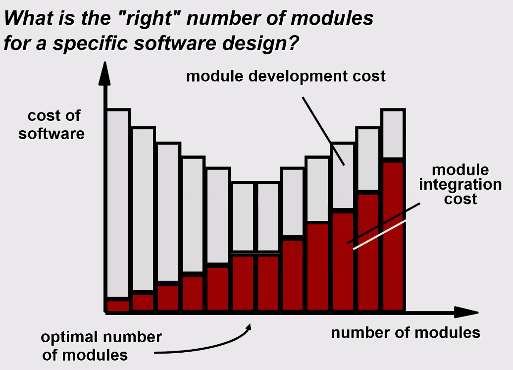
Modularity
- "modularity is the single attribute software that allows a program to be intellectually manageable"
- Monolithic software (i.e., a large program composed of a single module) cannot be easily grasped by a software engineer.
- In almost all instances, you should break the design into many modules, hoping to make understanding easier and as consequence, reduce the cost required to build the software.
Trade-offs
Interface Elements
- Interface is a set of operations that describes the externally observable behavior of a class and provides access to its public operations.
- Important elements
- User interface
- External interfaces to other systems
- Internal interfaces between carious design components
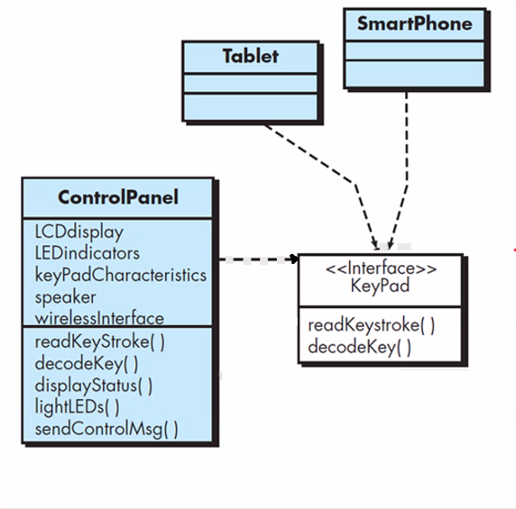 keypad provides interface to the user to interact with the application. Tablet, smart phone should implement KeyPad interface.
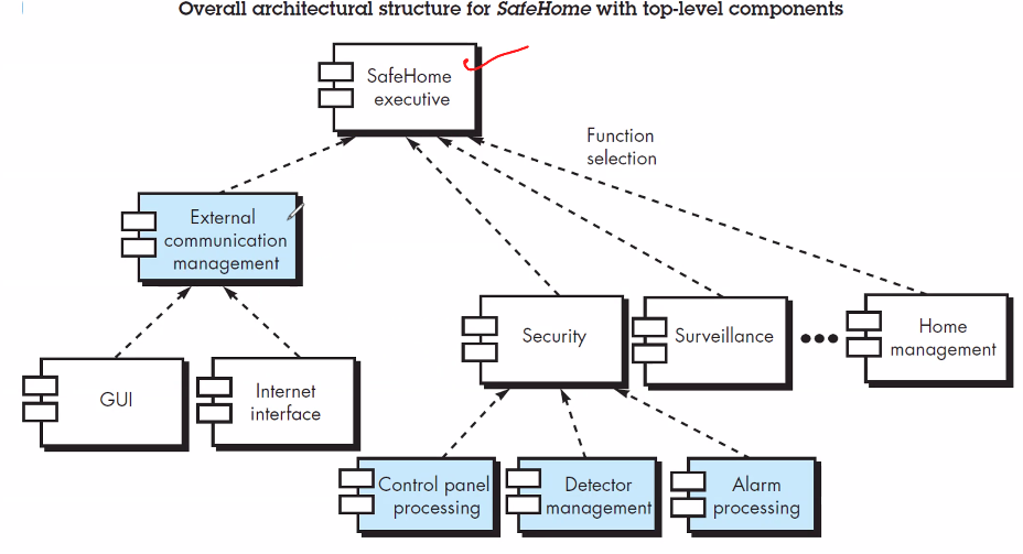
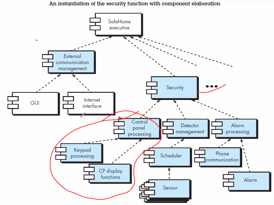
Component Elements
- Describes the internal detail of each software components
- Defines
- Data structures for all local data objects
- Algorithmic detail for all component processing
- Interface that allows access to all component operations.
- Modeled using UML component diagrams, UML activity diagrams, pseudo-code (PDL), and sometimes flowcharts.
[!inline]- Diagrams
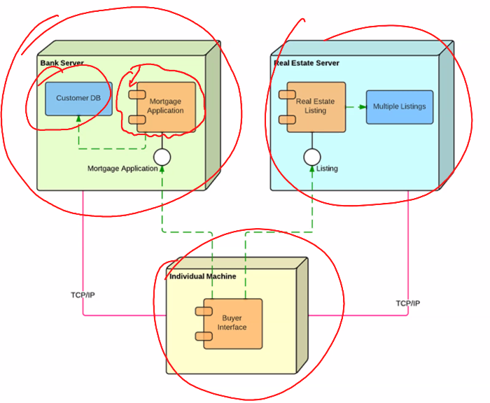
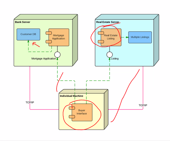
Deployment Elements
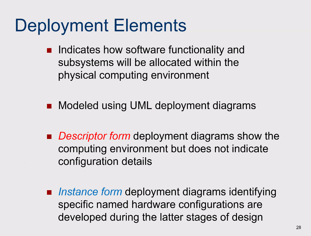
- Indicates how software functionality and subsystems will be allocated within the physical computing environment
- Modeled using UML deployment diagrams
- Descriptor form deployment diagrams show the computing environment but does not indicate configuration details
- Instance form deployment diagrams identifying specific named hardware configurations are developed during the latter stages of design.